Hi all. I’ve made quite a bit of progress on the truck since the last post (granted, that’s been quite a while), with the biggest accomplishment being the installation of the motor. Yes, that’s right, after all this time the motor is finally in. Want proof? Check out the pic:

Not bad, eh? It dropped right in, with only a minimal amount of shoehorning required. The design process of the adaptor plate and hub were the hardest parts. There is a fair amount of information about this on the internet, but most methods require a CAD system and "computer nerd" status. My method did involve some extra work, both on my part and on that of the machine shop, but it turned out pretty well in the end. Here’s how I did it:
I started by getting the hub made. The hub uses two setscrews, one over the key and the other 90 degrees to it, with lockscrews (a short setscrew installed behind the first setscrew, kind of like a locknut) and plenty of permanent (red) threadlocker. I’m really not concerned about the hub coming loose, and even if it does, I doubt it would damage anything; the clutch simply wouldn’t work properly.
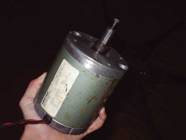
The pilot bearing from the crankshaft was installed in the hub in the proper location, as measured relative to the mounting surface of the crank. I would recommend installing this bearing for two reasons: 1) It greatly simplifies the alignment and drilling process of the adaptor plate, and 2) It should provide some extra support for the tranny shaft. It is very important to make sure that the trans shaft is going to clear the motor shaft when inserted into the pilot bearing. This can be done by observing the wear pattern on the trans shaft to see how far it was inserted into the pilot bearing. There should be a very distinct mark where the pilot bearing was. Here’s a bad pic of what the hub looked like when I got it back from the shop:

The next part was the plate itself, and the spacers. I decided to go with individual spacers to keep costs down. Since I’m intending to install a very comprehensive splash shield system, I’m not very concerned about debris getting into the clutch. The plate was designed using a method suggested by Larry (a fellow Mazda converter) on the EV photo album. I started by tracing the outline of the bell housing on a piece of posterboard and marking the approximate location of the trans shaft. I then cut this out and transferred it to another piece of posterboard, this time simplifying the outline of the bell housing and adding about half an inch all of the way around to allow for inaccuracies in measuring the location of the trans shaft. I then gave this to the machine shop. They cut the plate out of half inch aluminum and transferred the motor bolt pattern (centered around the location of the trans shaft, as marked by me) onto it.
At the same time, they also made the eight spacers, each 1" in diameter, out of steel. I determined the length of these spacers by measuring the distance from the flywheel mounting surface to the bell housing mounting surface, subtracting the length of the coupling, and adding the thickness of the plate (note that this only works if the back of the coupling sits flush with the back of the plate). This should give a negative value, but its absolute value is the length of the spacers.
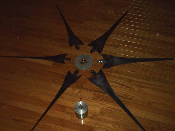
Here’s what the plate and spacers looked like at this point:

I then bolted the plate and spacers up to the motor, slid the coupling onto the motor shaft and stood the motor up on its endbell. I gently lowered the tranny down onto it. With a little fiddling, the trans shaft dropped right into the pilot bearing. Now, the trans shaft does have some play in it. I wanted to locate the tranny on the plate so that, when inserted into the pilot bearing, the trans shaft was at its center of movement. I did this by lifting the tranny up slightly (not enough to allow the trans shaft to come out of the pilot bearing) while my dad wiggled the tranny back and forth. When he found the center of movement, I simply let the tranny back down and marked all of the holes with transfer punches. I then removed the plate and drilled it. I also had to use a band saw and file to take a small chunk out of the plate where the clutch cylinder goes.
It was then time for the final assembly of the motor and tranny. With the motor still standing on its endbell, I bolted the flywheel to the coupling and then assembled the clutch on it, as shown below:

I then lowered the tranny down on to the motor and bolted them together. At this point, I had what I like to refer to as the "leaning tower of Mazda."

It was a simple matter to let the assembly down, hook it up to the hoist, and drop it into the truck. It is a lot easier to install the assembly with the stick removed. This is a simple procedure, and should yield no complications, as long as the opening where the stick was is covered up to keep dirt from getting inside. It also helps to have a friend work the hoist while you get in the engine compartment and guide the assembly down into the truck (carefully!).
Other developments to follow soon. I don’t have the time right now to write them up, and I doubt you have the time (or the attention span) to read it all in one installment! I know I wouldn’t... Stay tuned!


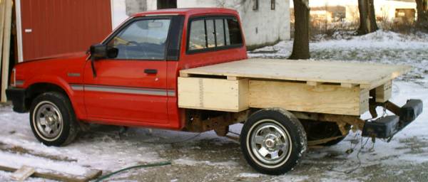
 The bed tilts to allow access to the batteries. The rear battery box, right behind the cab, will hold 16 batteries. The goal was to keep them as far forward as possible, for C.G. purposes. I still need to add some reinforcements to the battery box. I'm planning on putting two metal L-brackets on each corner, and a few along the bottom edges. There will also be angle iron running underneath on top of the mounts.
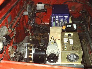

 I've been very busy lately, working on various projects (including this one). With school starting and everything I haven't been able to find the time to update this page. Hopefully now that I have things under control I'll be able to update this more often. I guess I'll just start where I left off:
